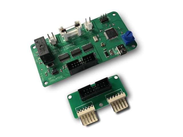
Features
12 optically isolated inputs
Dedicated input for replay knocker monitoring
11 adjustable time (0 to 30 second) inputs for solenoid/motor monitoring
Onboard 10A 12v supply relay
Up to 10A fused circuit protection
Serially controllable for ON/OFF/RESET with provided batch files and scripts
Included in Kit
1pc Solenoid Watchdog Control Board
1pc 16pin input ribbon cable – 6” (15cm)
1pc USB 2.0 Mini-B cable – 6' (1.8m)
Optional Accessories
1pc Input Breakout Adapter
2pcs 6pin input cable – 30” (76cm)
Theory of Operation
The Solenoid Watchdog is a control board designed to monitor high draw outputs that when left on for an extended period of time can damage the output stage of boards used to run force feedback in your cabinet. While it has been specifically designed to connect to the 24 port High Power Output Board from Zebsboards.com it can be used with just about any other board by utilizing the optional adapter and harness.
The board works by supplying the output voltage to the solenoids through a relay controlled by the onboard microcontroller. Optically isolated inputs are connected to the negative output stage of the 24 port High Power Output Board via the supplied ribbon cable (or directly to the negative side of the solenoid using the optional adapter and harnesses).
As outputs switch to the ON state corresponding timers are started and monitored in the microcontroller routine being referenced against the time set by the adjustable potentiometer on the board. As outputs switch to the OFF state, the corresponding timer is reset.
If any timer exceeds the preset limit, the output relay is turned off and the power is cut to the solenoids. The relay can only be restarted by either rebooting the USB connection or by a signal sent through the serial bus (see section on Serial Control for more information).
The board is capable of monitoring up to 11 inputs that are timed by the adjustable timer control potentiometer. The 12th input is preset to 100ms and is non-adjustable and is meant for monitoring a replay knocker. While it can be used for another purpose, be aware that the timer is preset for 100ms and cannot be changed.
Inputs are optically isolated from the microcontroller, protecting the microcontroller from voltage spikes, false readings and flyback voltages created by collapsing magnetic fields in the solenoids. The internal led in the optocoupler is connected to the input voltage to the board and the negative input from the output stage of the solenoid driver board. As an output switches to the ON state the negative side of the led closes, switching on the internal phototransistor which in turn passes a negative signal to the microcontroller. From there the monitoring routine does the rest of the work.
Timer adjustment is accomplished by converting the variable analog output of the potentiometer to a digital value that is calibrated to between 0 to 30 seconds across the full range of motion of the knob.
